Wednesday, October 23, 2019

Towed Water Speed Sensor - Ballast Weight

I had an application that needed to take an off-the-shelf water flow meter and allow it to be towed at various depths.  The lead time for similar items was more than I could afford and not quite what I was after.
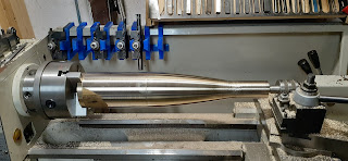
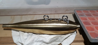
So I decided to make it.  After looking at options of sand casting in lead or bronze, 3D printing plugs and casting lead in plaster moulds and PU castings.  I decided a turned brass weight was the easiest approach for a one-off build.  A CNC lathe would have been perfect, but I haven't converted the lathe yet.  So I had to use a good old MS Excel spreadsheet to give co-ordinates and manually turn it using the digital read out on the lathe.

550mm of 101.6mm OD solid brass stock.  I was a surprised by the amount of run out and bend in the stock section, though I luckily had enough stock clearance.

The design was around a NACA 0021 section.  Picked for several reasons:
1. Convex surface all over, means easier to fair by hand over NACA 64xx sections
2. NACA 00xx series is a common all rounder with smooth drag "bucket"
3. 21% cord gave me the best compromise is stock length, diameter (cost) and what could fit on my lathe.


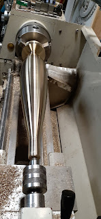
Starting the roughing


Fine step downs.


After smoothing step downs with a lathe file.


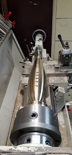
Starting of the forward sections.


After smoothing with the file


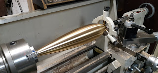
400 grit wet and dry finish


Drilling the adjustable anchor points so the axis of the tow line can be set forward of the centre of gravity during different tow angles/speeds.


Drilled and tapped.


Turning around to tap the fwd end.


Ready for equipment interface.


Anchor points installed.  Smaller, low profile fittings would be preferred.  The extra screws are used with cross drilled heads so locking wire can be used on the eye bolts.  This provides a positive lock against undoing during towing.


This simple commercial river water flow sensor uses an impeller, magnet and read switch to count revolutions per second. 


Giving it a first run on a mates boat.  


Tuesday, September 10, 2019

CNC Routing & Bending Aluminium Honeycomb, Toolpost Drilling/milling, Geeetech 3D printer & CNC Routing Steel

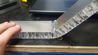
During the Hilux ute tray build I was experimenting with aluminium honeycomb panelling for ease of assembly.  I have used it at university in the FSAE race car team.

Here was some practice CNC Routing and bending pieces.


CNC routing a Western Red Cedar centreboard core for a carbon fibre centreboard on a sailing dinghy


Prototype front panels for electrical systems made on the CNC router from 4 mm aluminium plate.

Prototype parts from 12mm Aluminium plate on the CNC router.

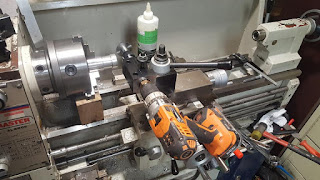
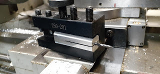
Making a Drilling & Milling attachment for the lathe tool post.  Using a COTS ER20 collet chuck with 16mm straight shank 150mm long.  The shaft was turned down for bearings and a standard boring bar quickchange tool post holder was bored out to accept the deep groove ball bearings.  Note: I expected these ball bearings to not provide enough rigidity to the setup, but have been very happy with the results.

Showing bearing assembly.  One the right hand side a shaft for the drill was pressed into the bore a secure with Loctite retaining compound.

Next step was to make an indexing plate and shaft lock for the spindle of the lathe. 

Spindle locking mechanism based on a "dynabolt" type wedging action inside the spindle bore.

First indexing plate made from 10mm thick HDPE.  It works very well, when I run into rigidity problems i'll upgrade the design to a 4-6mm aluminium plate. 

Drill can now be used at any angle with the compound slide and the chuck can be indexed.

First test piece.

Pretty happy with that.

Next job, small boring bar holder to hold small carbide end mills as boring bars.

Completed assembly.


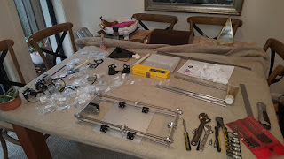
New Geeetech Aluminium i3 ProB 3D printer.  I've been using adative manufacturing at work for years, but it was time to start playing with alternative materials and designs at home. 


Out of the box there were plenty of issues ($250 kit printer is certainly the bottom end of the market).

I designed a new belt and bearing system for the Z-axis so they could be driven of a single more powerful Z-axis motor.  This ment that both leadscrews would always be synchronised and couldn't "rack" relative to each other.   

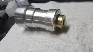
Practising my internal and external thread making on the metal lathe.


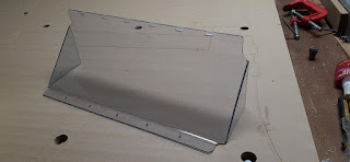
Building a DIY strip heater for bending plastics.  Using basic hardware store parts and a variable lab power supply.  The CNC router took care of the shape and profile.

Very happy with the first attempt.

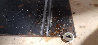
CNC Routing steel
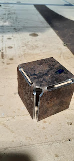
The first attempt didn't go so well...

With a bit of tuning I found the following was okay:
Tool - 1/8" single flute solid carbide
Spindle = 12,000 rpm
Feed = 600 mm/min
DOC = 0.2 mm per pass

Slow going, but okay for small parts. 

I tried an experimental technique for folding sheet metal parts.  How could I use a CNC router for part accuracy and still fold metal parts in the home shop without a press brake?  This seems like a viable solution.  If strength is needed, the folds could be welded up or braced internally.


Engagement Ring - CNC Router, Graphite Moulds, Bronze and Gold Casting

This section gives a snap shot of the design, CNC routing, casting and finishing of my fiance's engagement ring.

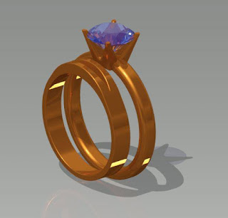
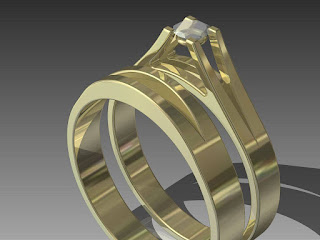
The first initial concept.

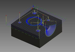
CAM tool profiles for CNC routing the 50x50x20mm graphite blocks. 

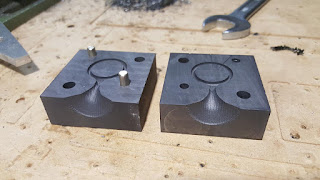
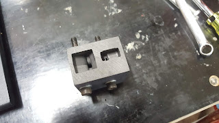
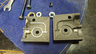
First set of completed moulds.
(Note: brass pins melted later on when I discovered that the mould needed quite a lot of pre-heat to get the metal to flow all the way around).

First cast with solder, showed that air pockets could form and prevent metal flow.

Design iteration 2:
The first attempt at matching the engagement ring to the existing wedding band

Mould set No.2 
The design incorporated a large sprue and riser section with the filling point entering at the bottom of the mould.  The two bolts used to hold it together used a conical seat for mould locating.

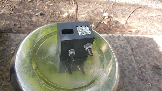
Mould held together with steel bolts.

First test cast using pure Tin.

Cast showing a successful melt.

An attempt with pure copper was undertaken.  Two problems were found. 1. Pure copper doesn't cast well, the metal doesn't flow well.  2. Borax seems to stick to the graphite and cause all sorts of issues.

The next cast I mixed up a Bronze alloy using 11% Tin and 89% Copper by weight.  This flowed a lot better.

First decent bronze cast.  The alloy was quite strong, hard and brittle.  Which with later research I found that copper based alloys tend to behave in an opposite way to steels.  When hardening copper based alloys, you let then cool slowly.  Where as annealing them is done by quenching them from a dull red down to room temperature.

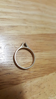
This one cleaned up okay.

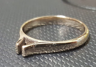
Polished even better.  Though it was found that trying to set a gem into this geometry was going to be difficult.  The design needed to be evolved.

Design iteration No.3
A six pronged type design was considered, where the CNC router could be used to do the accurate work.

Mould No.3
This mould used more flat sides where tapered tools could be used instead of 3D profiling with ball mills which greatly reduced the cycle time.

Moulds 1, 2 & 3

Bronze casting in mould No.3

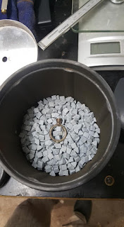
Casting trimmed and in the rock tumbler for a clean up.

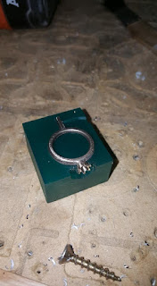
Held in a 3D printed fixture and CNC routing the prongs.

First attempt at the routed prongs.

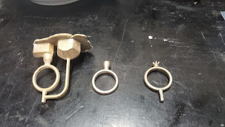
3 stage process of manufacturing the ring.

Design Iteration No.4
A final tweak to geometry and mould draft angle to aid release.

Moulds No.4 and a bronze casting.

As cast bronze

As machined bronze in CNC routed graphite fixture block.  Note the graphite block was machined to obtain higher accuracy than the earlier 3D printed fixture block design.

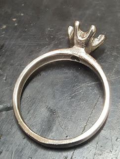
Hand trimmed bronze version.

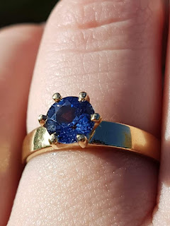
Australian Sapphire and 18k Yellow Gold selected.

Gold in the furnace ready for the first pour.

And it did not go so well....

All the preparation work of dialling in the bronze casting process, controlling pre-heat etc didn't seem to apply to the gold and I had to come at it with a revised casting strategy.

The mould was pre-heated to a glowing red hot, yet it still wasn't enough for complete flow.

I thought that perhaps the thermal conductivity of the graphite block was allowing heat to be leeched away via the contact surface with the heat proof mat.  So a lump of steel was pre-heated to a glowing red heat to act as a thermal mass / buffer for the mould to be placed on top of.  This was still not enough to give a good casting.

To obtain a successful casting, I had to place the whole graphite mould with the gold in it.  Into the furnace and allow the gold to melt in the mould itself.  This worked, but was risky if the mould spilt or split and mix the gold in with the dross and scrap metal in the bottom of the furnace. 

In addition to the thermal conductivity of the mould being and issue, the graphite crucible was also a problem.  As I lifted it out of the furnace the heat was able to leech out of the gold very quickly and reduce its fluidity before I could get it into the mould.


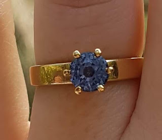
The end result was absolutely worth it though and we are both extremely happy with it.